System Overview
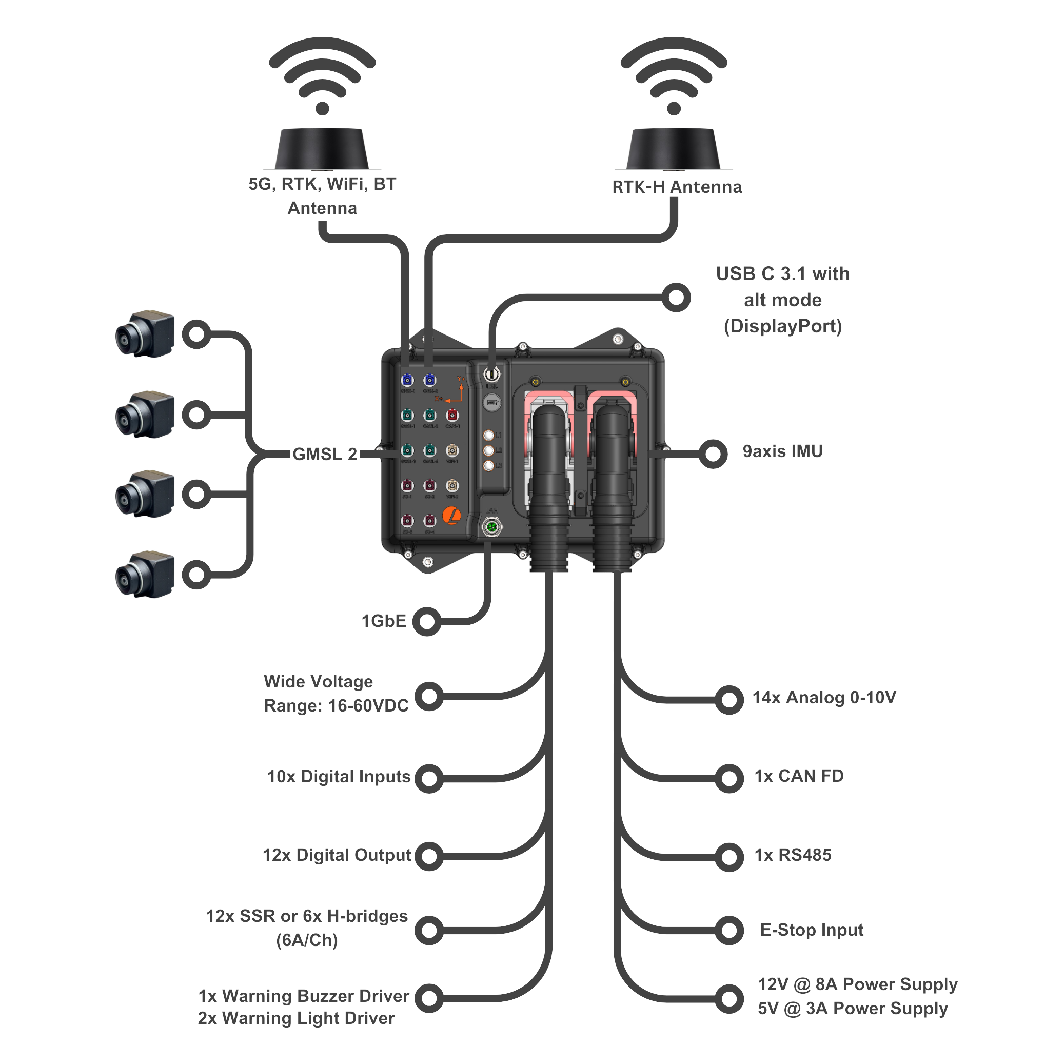
AutomatePro is a rugged, all-in-one ROS 2 platform designed for outdoor robotics and automation. It combines critical subsystems such as high-performance computing (with AI/ML acceleration), extensive I/O, an integrated 9-axis IMU and RTK GNSS, and robust IP67-rated housing. With support for 4G/5G, WiFi, Bluetooth, and a wide voltage input range, it provides a reliable and flexible foundation for advanced robotic applications. Pre-configured software tools ensure fast and seamless deployment.
The system’s integrated I/O significantly reduces the need for external components. Features include H-bridges or solid-state switches, digital and analog inputs/outputs, and support for warning systems (lights and sound). For navigation, it supports precise RTK GNSS (3–6 cm accuracy), dead reckoning via wheel inputs, differential heading, and satellite-based RTK correction—ideal for environments where magnetometers are unreliable.
AutomatePro supports a wide range of communication protocols including CAN, Ethernet, RS485, GMSL2, and USB 3.0. This makes it easy to connect with cameras, LIDARs, radars, motor controllers, and remote monitoring systems. Internally, it includes two regulated power outputs (12V and 5V) with voltage and current monitoring to support additional peripherals like sensors or actuators.
Available with four levels of compute based on the Nvidia Jetson Orin Series (from Nano 4GB to Orin NX 16GB), AutomatePro comes preloaded with JetPack 6.0 and ROS 2 drivers for all onboard hardware. These drivers are pre-installed and tested, offered by default in Docker containers for modular updates and maintenance. For advanced users, native host execution is also supported.
An overview of the AutomatePro
Features
Depending on the configuration, the AutomatePro can be equipped with the following features
Software:
- Base ROS 2 drivers for all sensors and IO
- Linux Ubuntu 22.04
- Jetpack 6.0
- 9 axis IMU (3 axis Compass, 3 axis Gyro, 3 axis Accelerometer)
- GNSS RTK positioning (Wheel tick and direction input optional)
- GNSS Heading
- 2x or 4x GMSL2 Camera Inputs with PoC (Power Over Coax)
- 10x Digital Inputs
- 12x Digital Outputs(~500mA)
- 12x Digital Drive software configurable as half or full-Bridge (7A)
- 14x Analog Inputs (0-10V or 4-20mA(on request))
- E-stop Input
- Warning Light and Buzzer Drivers
- 5G/4G Connectivity
- WiFi
- Bluetooth
- RS485
- CAN FD Bus
- 1GbE Ethernet
- USB 3.1 with Alt Mode for display port connection.
- 15.5V to 58V Supply Voltage Range
- Extensive power supply monitoring with current and voltage sensing on most onboard power supplies and all external facing supplies
- 12V 8A Onboard power supply for external systems
- 5V 3A onboard power supply for external systems
- IP67 water ingress protection
- Robust keyed connectors to prevent systems from being incorrectly connected
- Rapid development with dev tool kit
- Range of supported external sensors and components
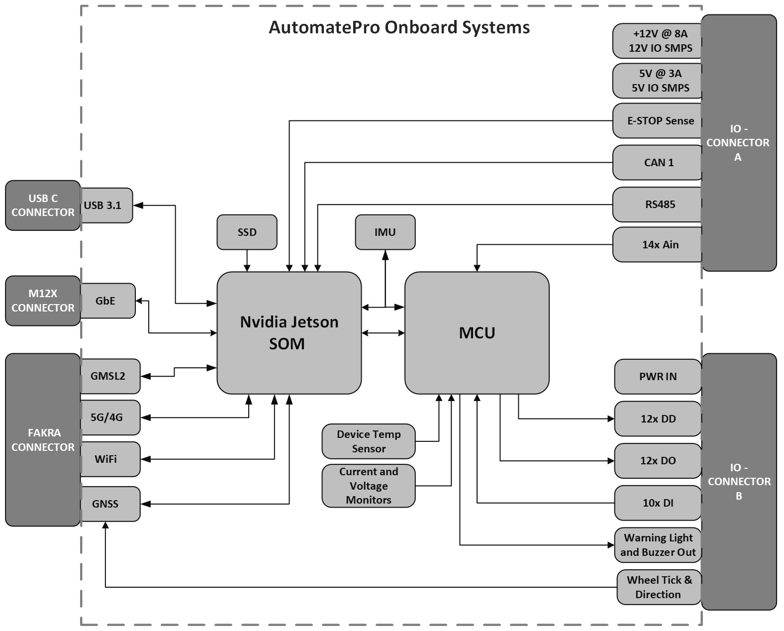
Hardware Architecture
A high level layout of the AutomatePro showing the interconnections of the different systems. The diagram shows most of the IO being controlled by the MCU while the high bandwidth systems such as GMSL, USB3, WiFi, GbE being feed directly to the Jetson SOM. Between the MCU and SOM is a communication bridge falicating the transfer of data. This bridge is initied on start-up
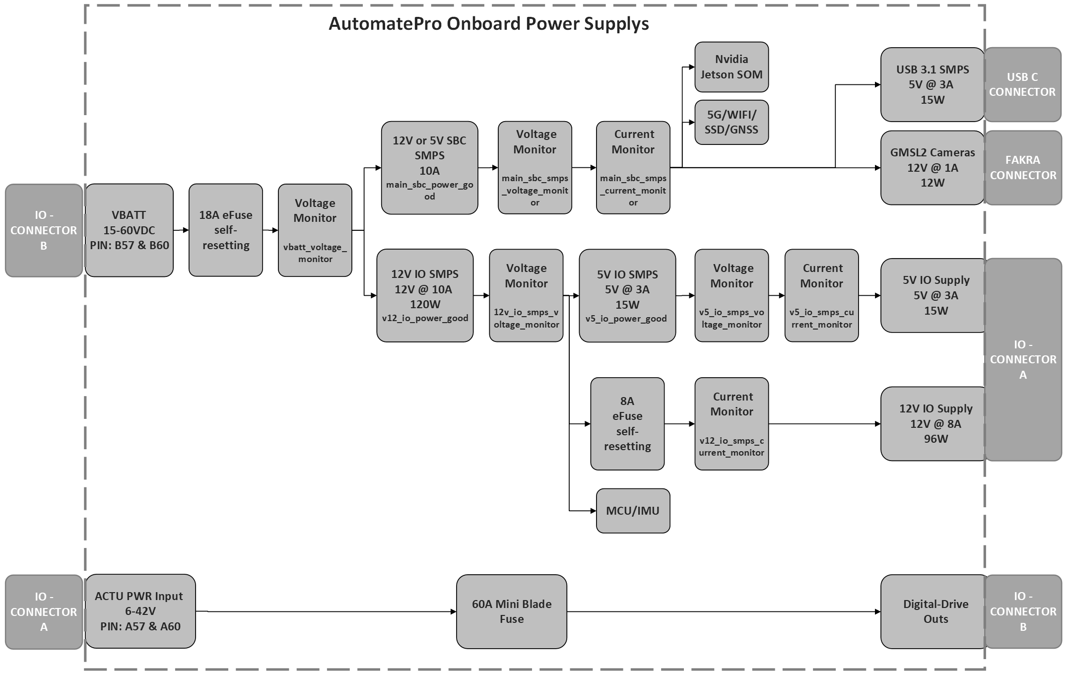
A simplified layout of the internal power’s supplies on the AutomatePro can be seen below - note, this only includes the power supplies that are relevant to the external systems and ignore regulators for onboards systems. The diagram also shows the onboard measurements of both current and voltage of the different rails along with onboard fuses.
Connector Pin Map & Functions
The two primary connectors used on the AutomatePro are from the TE Leavyseal connector series. The number allocation is given:
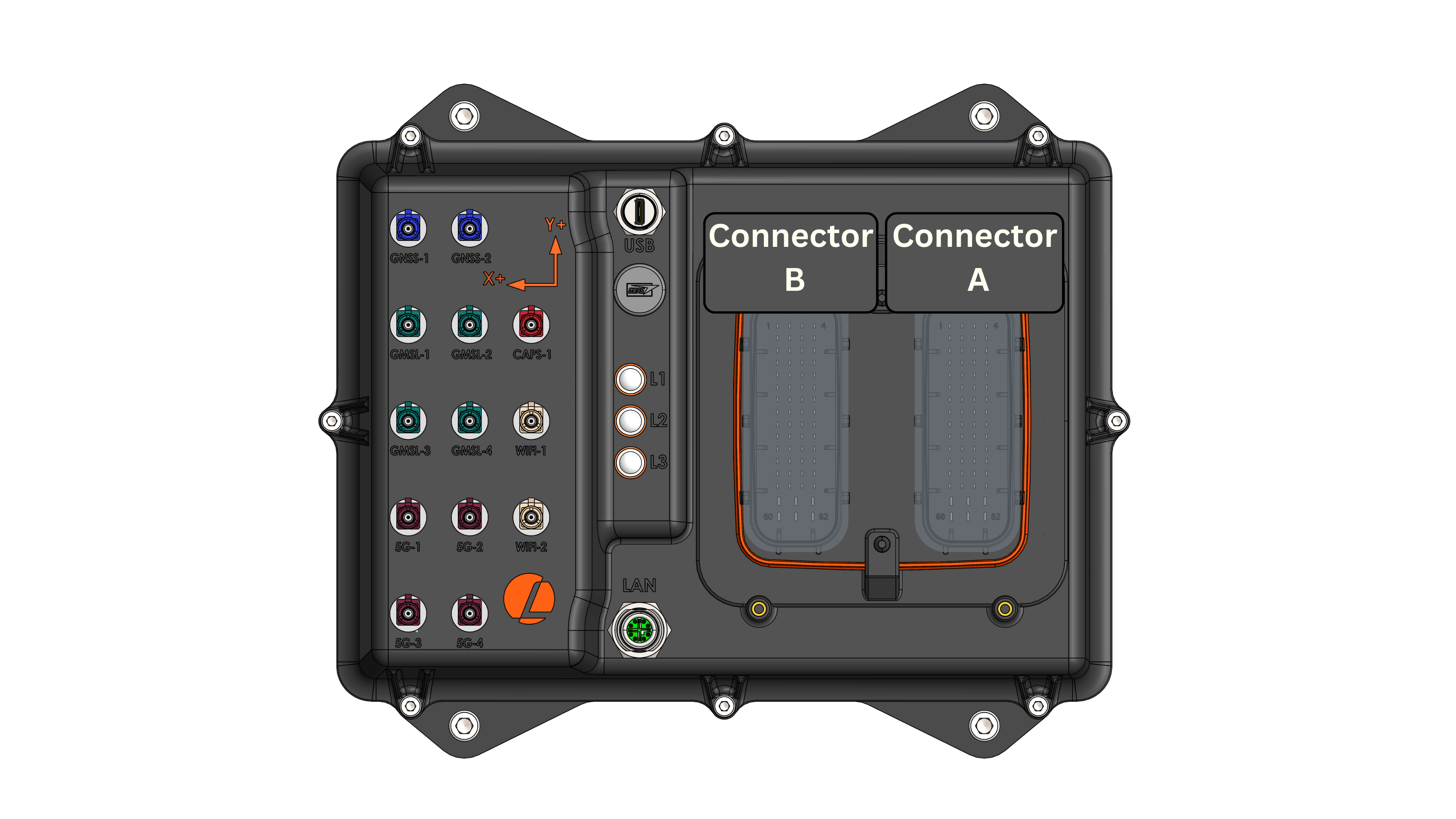
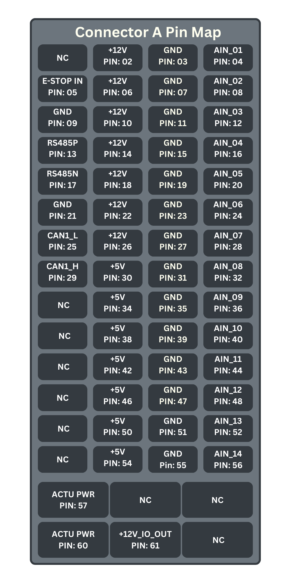
Connector A
| PIN NO. | PIN NAME | I/O TYPE | DESCRIPTION |
|---|---|---|---|
| A1 | NC | N/A | Not Connected |
| A2 | +12V | Power Out | 12V out with 0.75A self-resetting fuse |
| A3 | GND | Ground | Sensor Ground |
| A4 | AIN_01 | Input | 0-10V analog input (or 4-20mA on request) |
| A5 | E-STOP | Input | E-Stop button sensor for detecting when E-Stop has been pressed. |
| A6 | +12V | Power Out | 12V out with 0.75A self-resetting fuse |
| A7 | GND | Ground | Sensor Ground |
| A8 | AIN_02 | Input | 0-10V analog input (or 4-20mA on request) |
| A9 | GND | Ground | |
| A10 | +12V | Power Out | 12V out with 0.75A self resetting fuse |
| A11 | GND | Ground | Sensor Ground |
| A12 | AIN_03 | Input | 0-10V analog input (or 4-20mA on request) |
| A13 | RS485_P | Input/Output | RS485 serial communications |
| A14 | +12V | Power Out | 12V out with 0.75A self-resetting fuse |
| A15 | GND | Ground | Sensor Ground |
| A16 | AIN_04 | Input | 0-10V analog input (or 4-20mA on request) |
| A17 | RS485_N | Input/Output | RS485 serial communications |
| A18 | +12V | Power Out | 12V out with 0.75A self-resetting fuse |
| A19 | GND | Ground | Sensor Ground |
| A20 | AIN05 | Input | 0-10V analog input (or 4-20mA on request) |
| A21 | GND | Ground | |
| A22 | +12V | Power Out | 12V out with 0.75A self-resetting fuse |
| A23 | GND | Ground | Sensor Ground |
| A24 | AIN06 | Input | 0-10V analog input (or 4-20mA on request) |
| A25 | CAN1_L | Input/Output | CAN channel 1 communications |
| A26 | +12V | Power Out | 12V out with 0.75A self-resetting fuse |
| A27 | GND | Ground | Sensor Ground |
| A28 | AIN07 | Input | 0-10V analog input (or 4-20mA on request) |
| A29 | CAN1_H | Input/Output | CAN channel 1 communications |
| A30 | +5V | Power Out | 5V out with 0.75A self-resetting fuse |
| A31 | GND | Ground | Sensor Ground |
| A32 | AIN08 | Input | 0-10V analog input (or 4-20mA on request) |
| A33 | GND | Ground | |
| A34 | +5V | Power Out | 5V out with 0.75A self resetting fuse |
| A35 | GND | Ground | Sensor Ground |
| A36 | AIN09 | Input | 0-10V analog input (or 4-20mA on request) |
| A37 | CAN2_L | Input/Output | CAN channel 2 communications |
| A38 | +5V | Power Out | 5V out with 0.75A self-resetting fuse |
| A39 | GND | Ground | Sensor Ground |
| A40 | AIN10 | Input | 0-10V analog input (or 4-20mA on request) |
| A41 | CAN2_H | Input/Output | CAN channel 2 communications |
| A42 | +5V | Power Out | 5V out with 0.75A self-resetting fuse |
| A43 | GND | Ground | Sensor Ground |
| A44 | AIN11 | Input | 0-10V analog input (or 4-20mA on request) |
| A45 | GND | Ground | |
| A46 | +5V | Power Out | 5V out with 0.75A self-resetting fuse |
| A47 | GND | Ground | Sensor Ground |
| A48 | AIN12 | Input | 0-10V analog input (or 4-20mA on request) |
| A49 | NC | N/A | Do not connect |
| A50 | +5V | Power Out | 5V out with 0.75A self-resetting fuse |
| A51 | GND | Ground | Sensor Ground |
| A52 | AIN13 | Input | 0-10V analog input (or 4-20mA on request) |
| A53 | NC | N/A | Do not connect |
| A54 | +5V | Power Out | 5V out with 0.75A self-resetting fuse |
| A55 | GND | Ground | Sensor Ground |
| A56 | AIN14 | Input | 0-10V analog input (or 4-20mA on request) |
| A57 | ACTU_PWR | Power Input | Power Supply for all Digital Drives |
| A58 | NC | N/A | Do not connect |
| A59 | NC | N/A | Do not connect |
| A60 | ACTU_PWR | Power Input | Power Supply for all Digital Drives |
| A61 | +12V_IO_OUT | Power Out | +12V out with 8A self-resetting fuse - Used for any high current applications |
| A62 | NC | N/A | Do not connect |
Connector A - Pin map looking top down
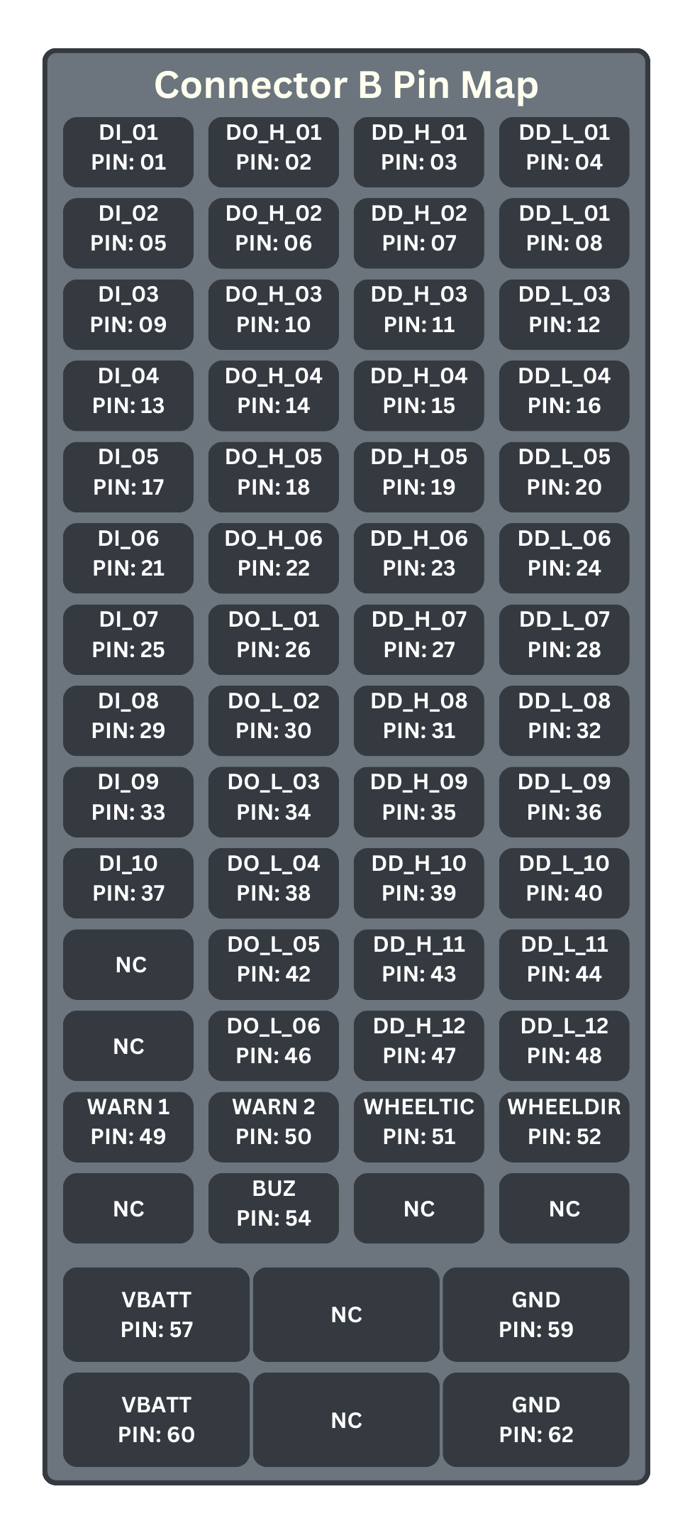
Connector B
| PIN NO. | PIN NAME | I/O TYPE | DESCRIPTION |
|---|---|---|---|
| B1 | DI_01 | Input | Digital Inputs |
| B2 | DO_H_01 | Output | Highside Digital Output @12V |
| B3 | DD_H_01 | Output | High Current Drive Output |
| B4 | DD_L_01 | Sink | High Current Sink |
| B5 | DI_02 | Input | Digital Inputs |
| B6 | DO_H_02 | Output | Highside Digital Output @12V |
| B7 | DD_H_02 | Output | High Current Drive Output |
| B8 | DD_L_02 | Sink | High Current Sink |
| B9 | DI_03 | Input | Digital Inputs |
| B10 | DO_H_03 | Output | Highside Digital Output @12V |
| B11 | DD_H_03 | Output | High Current Drive Output |
| B12 | DD_L_03 | Sink | High Current Sink |
| B13 | DI_04 | Input | Digital Inputs |
| B14 | DO_H_04 | Output | Highside Digital Output @12V |
| B15 | DD_H_04 | Output | High Current Drive Output |
| B16 | DD_L_04 | Sink | High Current Sink |
| B17 | DI_05 | Input | Digital Inputs |
| B18 | DO_H_05 | Output | Highside Digital Output @12V |
| B19 | DD_H_05 | Output | High Current Drive Output |
| B20 | DD_L_05 | Sink | High Current Sink |
| B21 | DI_06 | Input | Digital Inputs |
| B22 | DO_H_06 | Output | Highside Digital Output @12V |
| B23 | DD_H_06 | Output | High Current Drive Output |
| B24 | DD_L_06 | Sink | High Current Sink |
| B25 | DI_07 | Input | Digital Inputs |
| B26 | DO_L_01 | Sink | Low side Sink |
| B27 | DD_H_07 | Output | High Current Drive Output |
| B28 | DD_L_07 | Sink | High Current Sink |
| B29 | DI_08 | Input | Digital Inputs |
| B30 | DO_L_02 | Sink | Low side Sink |
| B31 | DD_H_08 | Output | High Current Drive Output |
| B32 | DD_L_08 | Sink | High Current Sink |
| B33 | DI_09 | Input | Digital Inputs |
| B34 | DO_L_03 | Sink | Low side Sink |
| B35 | DD_H_09 | Output | High Current Drive Output |
| B36 | DD_L_09 | Sink | High Current Sink |
| B37 | DI_10 | Input | Digital Inputs |
| B38 | DO_L_04 | Sink | Low side Sink |
| B39 | DD_H_10 | Output | High Current Drive Output |
| B40 | DD_L_10 | Sink | High Current Sink |
| B41 | NC | N/A | Not Connected |
| B42 | DO_L_05 | Sink | Low side Sink |
| B43 | DD_H_11 | Output | High Current Drive Output |
| B44 | DD_L_11 | Sink | High Current Sink |
| B45 | NC | N/A | Not Connected |
| B46 | DO_L_06 | Sink | Low side Sink |
| B47 | DD_H_12 | Output | High Current Drive Output |
| B48 | DD_L_12 | Sink | High Current Sink |
| B49 | WARNING_LIGHT_1 | Sink | High Current Sink for connecting external light |
| B50 | WARNING_LIGHT_2 | Sink | High Current Sink for connecting external light |
| B51 | WHEEL_TICK | Input | Non standard. Contact Lemvos for more information |
| B52 | WHEEL_DIRECTION | Input | Non standard. Contact Lemvos for more information |
| B53 | NC | N/A | Not Connected |
| B54 | WARNING_BUZZER | Sink | High Current Sink for connecting external warning buzzer/alarm |
| B55 | NC | N/A | Not Connected |
| B56 | NC | N/A | Not Connected |
| B57 | VBATT | Power Input | Provides Power to the AutomatePro |
| B58 | NC | N/A | Not Connected |
| B59 | GND | Ground | AutomatePro ground |
| B60 | VBATT | Power Input | Provides Power to the AutomatePro |
| B61 | NC | N/A | Not Connected |
| B62 | GND | Ground | AutomatePro ground |
Connector B - Pin map looking top down
Operating Conditions
The table provides both the absolute maximum and minimum limits, as well as the recommended operating conditions. It is strongly advised that nominal operations remain within the recommended operating values.
| DESCRIPTION | ABSOLUTE MAX/MINS | RECOMMENDED OPERATING VALUES | UNITS | TOLERANCE |
|---|---|---|---|---|
| Main AutomatePro Power Input [VBATT] | ||||
| Supply Voltage Range | 15.00-60 | 15.5-58 | VDC | |
| Expected Power Consumption | 10-200¹ | W | ||
| Actuator Power Input (Digital Drive) [ACTU_PWR] | ||||
| Voltage Range | 6-60 | 7-42 | VDC | |
| Max Current | 60 | 55 | A | |
| IO 5V Supply Output [+5V] | ||||
| Output Voltage | - | 5 | VDC | 0.5 |
| Current Cutoff | - | 3 | A | |
| IO 12V Supply Output [+12V] | ||||
| Output Voltage | - | 12 | VDC | 0.5 |
| Current Cutoff | - | 8 | A | |
| Digital Output [DO_H_01-06] | ||||
| Output Voltage | - | 12.0 | VDC | 0.5 |
| Max Current Source | - | 600.0 | mA | |
| PWM Frequency | - | 0.5 | kHz | |
| Duty Cycle | - | 0-100 | % | |
| Software Response Rate | - | 200.0 | ms | |
| Digital Output [DO_L_01-06] | ||||
| Sink Voltage | 0-60 | 0-42 | VDC | |
| Max Current Sink | 1000 | 600.0 | mA | |
| PWM Frequency (DO_L_01-04) | - | 15.0 | kHz | |
| Duty Cycle | - | 0-100 | % | |
| Software Response Rate | - | 200.0 | ms | |
| Digital Drive [DD_x_xx] | ||||
| Drive Voltage | 6-60 | 7-42 | VDC | |
| Rated Current/Channel | 7 | 5.0 | A | |
| PWM Frequency | - | 15.0 | kHz | |
| Duty Cycle | - | 0-100 | % | |
| Software Response Rate | - | 200.0 | ms | |
| Warning System | ||||
| Drive Voltage | 0-40 | 0-24 | VDC | |
| Rated Current/Channel | 5 | 3.0 | A | |
| Software Response Rate | - | 200.0 | ms | |
| Analog Inputs [AIN_xx] | ||||
| Input Voltage | 0-12 | 0-10 | VDC | |
| Sample Rate | - | 30.0 | Hz | |
| Digital Input [DI_xx] | ||||
| Input Voltage Range | 5-30 | 5-24 | VDC | 1 |
| Max Sample Rate | - | 10 | Hz | |
| Environmental | ||||
| Operational Temperature Range | -20 to +45² | °C | ||
| Ingress Protection | IP67 | - | ||
| Mass | 2.2 | kg | ||
1 The power consumption is highly dependent on the external systems attached - without any external systems connected the max consumption is < 30W(NX 16GB).
2 Extended temperature device exists, contact lemvos for more information
LED Functions
| LED Designator | LED Colour | Function |
|---|---|---|
| L1 | GREEN | Power Good - checks all onboard power supplies |
| L1 | BLUE | WIFI - WLAN |
| L1 | RED | nE-STOP - LED will be off when E-STOP is pressed (E-STOP input low) |
| L2 | BLUE | Ethernet Link |
| L2 | RED | Ethernet ACT |
| L3 | GREEN | SSD Read/Write LED |
| L3 | BLUE | WWAN - 5G RF function is on |
| L3 | RED | WIFI - Bluetooth |

Dimensions
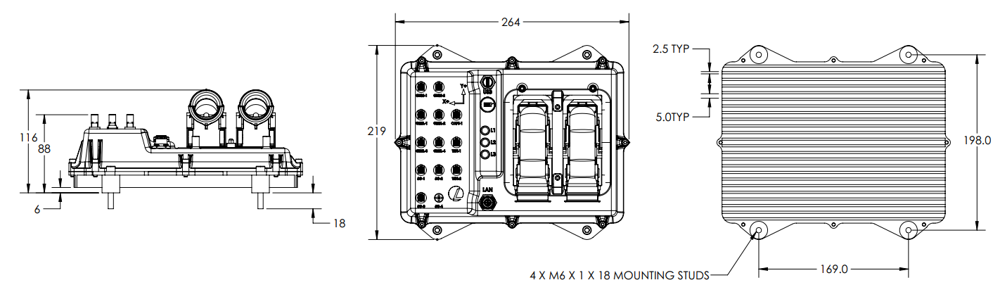
All dimensions are in millimeters (mm).
Compute Modules
AutomatePro supports a range of NVIDIA Jetson Orin modules, each catering to different performance and resource requirements.
Supported NVIDIA Jetson Orin Modules
- Jetson Orin Nano 4GB
- Jetson Orin Nano 8GB
- Jetson Orin NX 8GB
- Jetson Orin NX 16GB
For more information on the performance of the different modules, please refer to the Jetson Orin Series Page
Software Architecture
OS
AutomatePro operates on Jetson Linux 36.3, which features the Linux Kernel 5.15 and an Ubuntu 22.04 based root filesystem. This OS is optimized for the NVIDIA Jetson platform and includes all necessary drivers and libraries pre-installed, ensuring seamless integration and performance.
For more information, refer to the NVIDIA Developer Guide
Jetson Linux 36.3 is part of the NVIDIA JetPack SDK (ver. 6.0), which provides a comprehensive set of tools and libraries for developing end-to-end accelerated AI and ML applications on the Jetson platform.
The kernel is configured with the PREEMPT_RT patch to ensure low-latency and high-priority task execution, which is crucial for real-time robotics applications. For more information on the PREEMPT_RT patch, refer to the official documentation.
AutomatePro is pre flashed with the compatible OS. However, if required, the OS can be manually flashed. Refer to the flashing guide for detailed instructions.
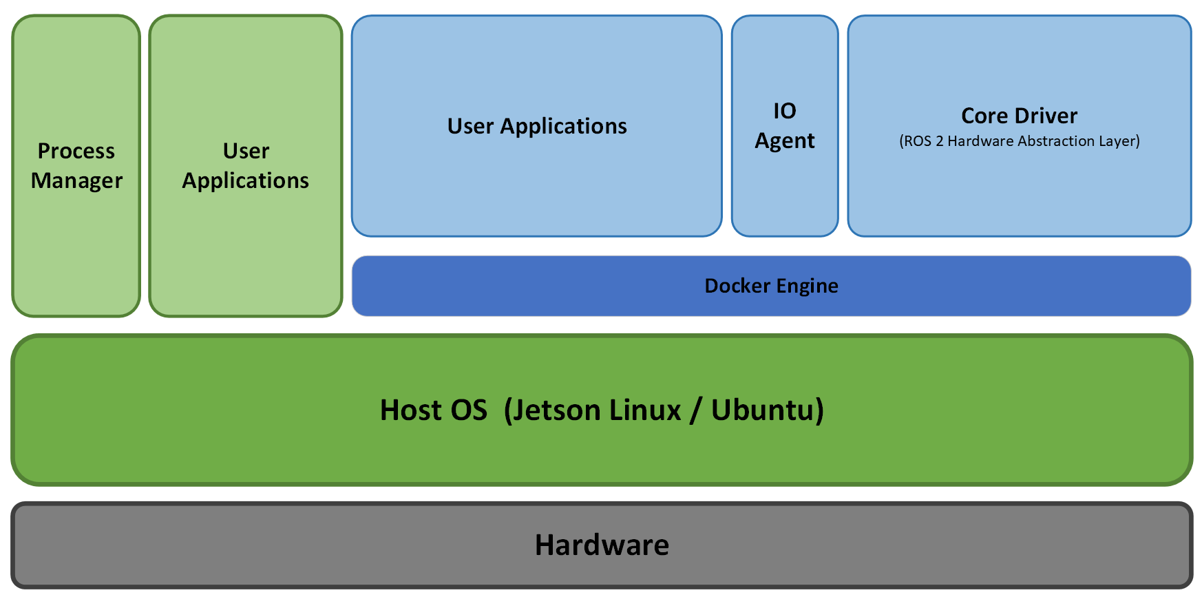
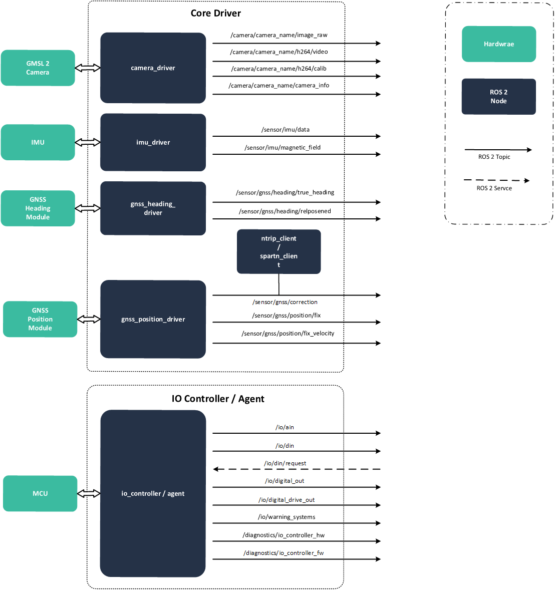
ROS 2
AutomatePro is ROS 2 native and provides necessary abstractions to interact with the hardware. Below is a high-level overview of the ROS 2 nodes.
Docker
AutomatePro leverages Docker for containerized deployment, enhancing ease of deployment, scalability, and management.
Containers
By default, all ROS 2 nodes and other services run in Docker containers. However, it is also possible to run the nodes directly on the host system if required.
All the docker compose files can be found in the ~/.automatepro directory. These are further orchestrated using systemd services.
automatepro-core-driver.service- Core driver nodes for handling GNSS, IMU, Cameras, etc.automatepro-io-agent.service- IO agent for handling digital and analog I/Os, warning systems, etc.automatepro-ros-utils.service- ROS 2 utilities such as foxglove bridge, visualization nodes, etc.
Core Driver
automatepro-core-driver container is responsible for running all the essential drivers abstracting the hardware to the ROS 2 nodes.
IO Agent
The automatepro-io-agent container is responsible for the communication between ROS 2 and the micro-ROS nodes running on the MCU, which handles analog and digital I/Os, warning systems, etc.
Refer the links for more details on IO capabilities.
ROS Utils
automatepro-ros-utils container is responsible for running the ROS 2 utilities such as foxglove bridge, visualization nodes, etc.
This will help you to get started as shown in the Quick Start Guide. It is recommended to remove this container in production with following command:
sudo systemctl disable automatepro-ros-utils.service
docker rm -f automatepro-ros-utils