IMU
Hardware
AutomatePro includes an onboard BNO085 9-axis MEMS IMU. The IMU combines a 3-axis accelerometer, 3-axis gyroscope, and 3-axis magnetometer. The driver publishes ROS 2 IMU data and, when enabled, magnetic-field and accuracy data.
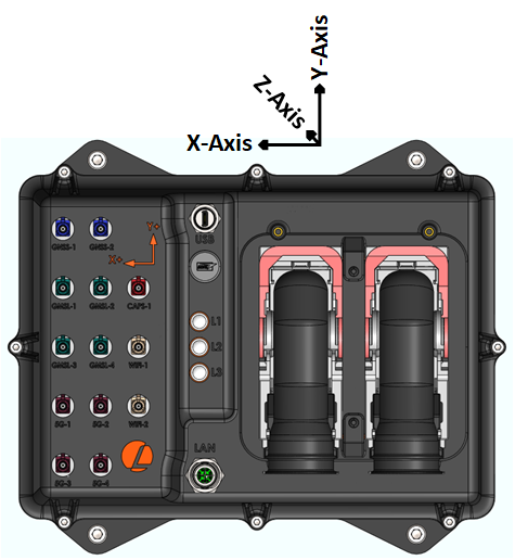
The arrows on the device indicate the IMU vector directions:
IMU Specifications
| Parameter | Value |
|---|---|
| Sensor | BNO085 |
| Sensing types | 3-axis gyroscope, 3-axis magnetometer, 3-axis accelerometer |
| Rotation vector error (dynamic)1 | 3.5 deg |
| Accelerometer accuracy1 | 0.3 m/s2 |
| Gyroscope accuracy1 | 3.1 deg/s |
| Magnetometer accuracy1 | 1.4 uT |
| Default IMU sample rate | 100 Hz |
| Configurable IMU rate | Up to 400 Hz, hardware dependent |
1 Based on IC manufacturer tests. Results on AutomatePro can vary by mounting, calibration, and magnetic environment. See the BNO080/BNO085 datasheet for manufacturer details.
ROS API
Node: automatepro_imu_driver
Publishers
| Topic | Type | Description |
|---|---|---|
/sensor/imu/data | sensor_msgs/msg/Imu | Orientation, angular velocity, and linear acceleration. |
/sensor/imu/magnetic_field | sensor_msgs/msg/MagneticField | Magnetic field data, when magnetometer publishing is enabled. |
/sensor/imu/accuracy | automatepro_imu_driver/msg/ImuAccuracy | Accuracy levels for orientation, accelerometer, gyroscope, and magnetic-field reports. |
Services
| Service | Type | Description |
|---|---|---|
/sensor/imu/save_tare | std_srvs/srv/Trigger | Persists the current tare to sensor flash. |
/sensor/imu/save_calibration | std_srvs/srv/Trigger | Saves Dynamic Calibration Data (DCD) to sensor flash. |
/sensor/imu/reinit | std_srvs/srv/Trigger | Reinitializes the IMU driver and sensor. |
Verify IMU Data
Run these checks from AutomatePro over SSH:
source /opt/ros/humble/setup.bash
ros2 node list | grep automatepro_imu_driver
ros2 topic echo /sensor/imu/data --once --qos-reliability best_effort
If accuracy publishing is enabled, check calibration state:
ros2 topic echo /sensor/imu/accuracy --once
Accuracy levels use:
| Value | Meaning |
|---|---|
0 | Unreliable |
1 | Low |
2 | Medium |
3 | High |
255 | Unknown |
Configuration
Driver: automatepro_imu_driver
Container: automatepro-core-driver
Runtime ROS configuration is stored in /opt/automatepro/config/ros. Packaged defaults are stored in /opt/automatepro/defconfig/ros.
Edit the IMU parameter file:
sudo nano /opt/automatepro/config/ros/imu_params.yaml
Important parameters:
| Parameter | Default | Description |
|---|---|---|
log_level | info | Driver log level. Launch accepts debug, info, warn, error, or fatal. |
frame_id | lm450_imu_link | Frame ID stamped on published IMU messages. |
rotation_vector_mode | game_rotation_vector | Orientation report type. Use rotation_vector for magnetic absolute heading, game_rotation_vector for relative heading without magnetometer, or geomagnetic_rotation_vector for geomagnetic heading. |
tare.on_startup | false | Applies one-shot tare when the node starts. Leave disabled after commissioning. |
tare.axes | xyz | Axes included in tare. |
tare.persist | false | Saves tare to flash when enabled. |
tare.orientation.enabled | true | Applies the configured chip-to-body orientation mapping at startup and watchdog reinitialization. |
tare.orientation.use_quaternion | false | Uses qx, qy, qz, and qw instead of roll, pitch, and yaw when enabled. |
tare.orientation.qx/qy/qz/qw | 0/0/0/1 | Quaternion orientation mapping when use_quaternion is true. |
calibration.accelerometer.enabled | true | Enables BNO08x accelerometer dynamic calibration. |
calibration.accelerometer.planar | false | Enables planar accelerometer calibration mode. |
calibration.gyroscope.enabled | true | Enables BNO08x gyroscope dynamic calibration. |
calibration.gyroscope.on_table | true | Enables stationary on-table gyroscope calibration assist. |
calibration.magnetic_field.enabled | false | Enables BNO08x magnetometer dynamic calibration. Enable only when magnetic heading is required and the environment is suitable. |
calibration.save_dcd | true | Periodically saves Dynamic Calibration Data to flash. |
i2c.enabled | true | Uses I2C communication. |
i2c.bus | /dev/i2c-7 | I2C bus path. |
i2c.address | 0x4B | BNO08x I2C address. |
uart.enabled | false | Uses UART communication instead of I2C when enabled. |
uart.device | /dev/ttyACM0 | UART device path when UART transport is enabled. |
publish.accuracy.enabled | true | Publishes /sensor/imu/accuracy. |
publish.imu.enabled | true | Publishes /sensor/imu/data. |
publish.imu.rate | 100 | Requested IMU report rate in Hz. |
publish.magnetic_field.enabled | false | Publishes /sensor/imu/magnetic_field. Use --qos-reliability best_effort when echoing this topic from the CLI. |
publish.magnetic_field.rate | 100 | Requested magnetometer report rate in Hz. |
publish.imu.orientation_offset.enabled | false | Applies a software quaternion offset before publishing orientation. |
Restart automatepro-core-driver after changing the configuration. Configuration values are loaded when the driver container starts and are only applied after the service restarts.
sudo systemctl restart automatepro-core-driver
Default Configuration Shape
automatepro_imu_driver:
  ros__parameters:
    log_level: "info"
    frame_id: "lm450_imu_link"
    rotation_vector_mode: "game_rotation_vector"
    tare:
      on_startup: false
      axes: "xyz"
      persist: false
      orientation:
        enabled: true
        roll_deg: 0.0
        pitch_deg: 0.0
        yaw_deg: -80.0
        use_quaternion: false
        qx: 0.0
        qy: 0.0
        qz: 0.0
        qw: 1.0
    calibration:
      accelerometer:
        enabled: true
        planar: false
      gyroscope:
        enabled: true
        on_table: true
      magnetic_field:
        enabled: false
      save_dcd: true
    i2c:
      enabled: true
      bus: "/dev/i2c-7"
      address: "0x4B"
    uart:
      enabled: false
      device: "/dev/ttyACM0"
    publish:
      accuracy:
        enabled: true
      magnetic_field:
        enabled: false
        rate: 100
      imu:
        enabled: true
        rate: 100
Example
This example prints IMU and magnetic-field messages by subscribing to /sensor/imu/data and /sensor/imu/magnetic_field.
The tutorial package is available in the AutomatePro tutorials repository.
- Python
- C++
import rclpy
from rclpy.node import Node
from sensor_msgs.msg import Imu, MagneticField


class ImuSubscriber(Node):
    def __init__(self):
        super().__init__("imu_subscriber")
        self.imu_subscription = self.create_subscription(
            Imu,
            "/sensor/imu/data",
            self.imu_callback,
            10,
        )
        self.magnetic_field_subscription = self.create_subscription(
            MagneticField,
            "/sensor/imu/magnetic_field",
            self.magnetic_field_callback,
            10,
        )

    def imu_callback(self, msg):
        self.get_logger().info(
            "Received IMU message: orientation=%s, angular_velocity=%s, linear_acceleration=%s"
            % (msg.orientation, msg.angular_velocity, msg.linear_acceleration)
        )

    def magnetic_field_callback(self, msg):
        self.get_logger().info(
            "Received MagneticField message: magnetic_field=%s" % msg.magnetic_field
        )


def main(args=None):
    rclpy.init(args=args)
    node = ImuSubscriber()
    rclpy.spin(node)
    node.destroy_node()
    rclpy.shutdown()


if __name__ == "__main__":
    main()
Run the node:
ros2 run automatepro_py_tutorials imu_node
#include <memory>

#include <rclcpp/rclcpp.hpp>
#include <sensor_msgs/msg/imu.hpp>
#include <sensor_msgs/msg/magnetic_field.hpp>

class ImuSubscriber : public rclcpp::Node
{
public:
  ImuSubscriber()
  : Node("imu_subscriber")
  {
    imu_subscription_ = this->create_subscription<sensor_msgs::msg::Imu>(
      "/sensor/imu/data",
      10,
      std::bind(&ImuSubscriber::imu_callback, this, std::placeholders::_1));

    magnetic_field_subscription_ =
      this->create_subscription<sensor_msgs::msg::MagneticField>(
        "/sensor/imu/magnetic_field",
        10,
        std::bind(&ImuSubscriber::magnetic_field_callback, this, std::placeholders::_1));
  }

private:
  void imu_callback(const sensor_msgs::msg::Imu::SharedPtr msg) const
  {
    RCLCPP_INFO(
      this->get_logger(),
      "Received IMU message: orientation=[x: %f, y: %f, z: %f, w: %f], angular_velocity=[x: %f, y: %f, z: %f], linear_acceleration=[x: %f, y: %f, z: %f]",
      msg->orientation.x, msg->orientation.y, msg->orientation.z, msg->orientation.w,
      msg->angular_velocity.x, msg->angular_velocity.y, msg->angular_velocity.z,
      msg->linear_acceleration.x, msg->linear_acceleration.y, msg->linear_acceleration.z);
  }

  void magnetic_field_callback(const sensor_msgs::msg::MagneticField::SharedPtr msg) const
  {
    RCLCPP_INFO(
      this->get_logger(),
      "Received MagneticField message: magnetic_field=[x: %f, y: %f, z: %f]",
      msg->magnetic_field.x, msg->magnetic_field.y, msg->magnetic_field.z);
  }

  rclcpp::Subscription<sensor_msgs::msg::Imu>::SharedPtr imu_subscription_;
  rclcpp::Subscription<sensor_msgs::msg::MagneticField>::SharedPtr magnetic_field_subscription_;
};

int main(int argc, char * argv[])
{
  rclcpp::init(argc, argv);
  rclcpp::spin(std::make_shared<ImuSubscriber>());
  rclcpp::shutdown();
  return 0;
}
Run the node:
ros2 run automatepro_cpp_tutorials imu_node
Orientation Commissioning
Use this workflow when the IMU is remounted, when the reference orientation changes, or when a system needs a known rest pose.
Perform tare and calibration only when the device is in its final mounting position and away from motors, steel structures, strong magnets, and current-carrying wires.
-
Complete dynamic calibration.
Move the device through several stable orientations for accelerometer calibration, leave it stationary for gyroscope calibration, and perform magnetic rotations only if magnetic-field calibration is enabled and required.
-
Tare the reference pose.
Place AutomatePro in the desired zero orientation. Temporarily set:
tare:
  on_startup: true
  axes: "xyz"
  persist: true
Restart the core driver and wait for tare completion in logs:
sudo systemctl restart automatepro-core-driver
sudo journalctl -u automatepro-core-driver -f
After tare completes, set
tare.on_startup: falseso it is not applied on every boot. -
Set mounting orientation.
Use
tare.orientation.roll_deg,pitch_deg, andyaw_degto map the chip axes to the device body frame. This orientation mapping is re-applied on startup and watchdog recovery. -
Apply software heading offset when needed.
If the device in the rest pose should publish identity orientation
(0, 0, 0, 1), capture the current quaternion:ros2 topic echo /sensor/imu/data --field orientation --onceSet
publish.imu.orientation_offset.*to the conjugate of that quaternion and enablepublish.imu.orientation_offset.enabled. -
Verify the final output.
Restart the core driver and verify that the rest pose and motion directions match your robot frame:
sudo systemctl restart automatepro-core-driver
ros2 topic echo /sensor/imu/data --field orientation --once
Developer Notes: rotation modes and persistence
rotation_vector_mode selects which BNO08x SH-2 report is enabled. game_rotation_vector does not use the magnetometer and reports relative heading. rotation_vector and geomagnetic_rotation_vector use magnetic information for heading.
Dynamic tare runs only on initial node startup when tare.on_startup is enabled. The fixed mounting orientation is re-applied on every sensor initialization, including watchdog recovery. The software orientation offset is applied as q_published = q_offset * q_sensor.
Troubleshooting
IMU Topic Is Missing
Check that the driver is enabled:
grep ROS_DRIVER_IMU /opt/automatepro/.env
Check logs:
sudo journalctl -u automatepro-core-driver -n 100 --no-pager
Orientation Is Correct After Startup but Wrong After Recovery
Verify tare.orientation.enabled: true. The fixed orientation mapping is the part reapplied on every sensor initialization.
Heading Drifts or Jumps
Check the rotation-vector mode and magnetic environment. If the system does not require magnetic absolute heading, game_rotation_vector is less sensitive to magnetic disturbances. If magnetic heading is required, calibrate in the deployment environment and monitor /sensor/imu/accuracy.