Quick Start Guide
Welcome to AutomatePro. This guide provides clear, step-by-step instructions to help you set up and begin using your AutomatePro system quickly.
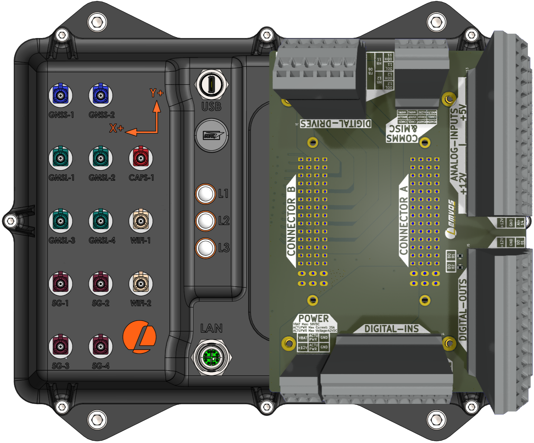
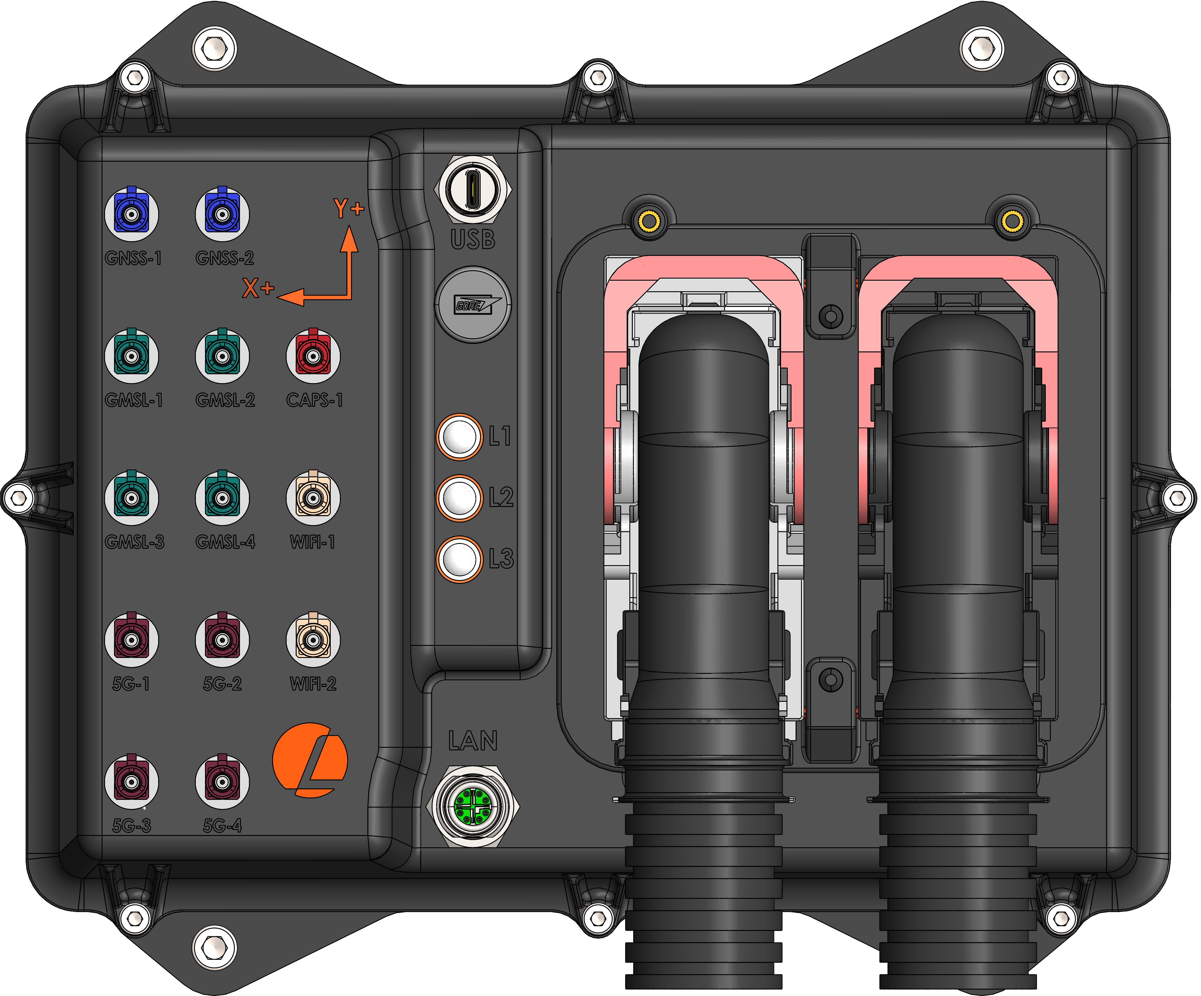
AutomatePro offers two connection options. The production version uses TE Leavyseal connectors for full IP67 protection. The development-board option is intended for prototyping and rapid development, using terminal blocks for easier connectivity.
Both options are interchangeable; however, this Quick Start Guide uses the development-board version for easier prototyping and wiring.
AutomatePro with Development Board
AutomatePro with TE Leavyseal
What's in the Box
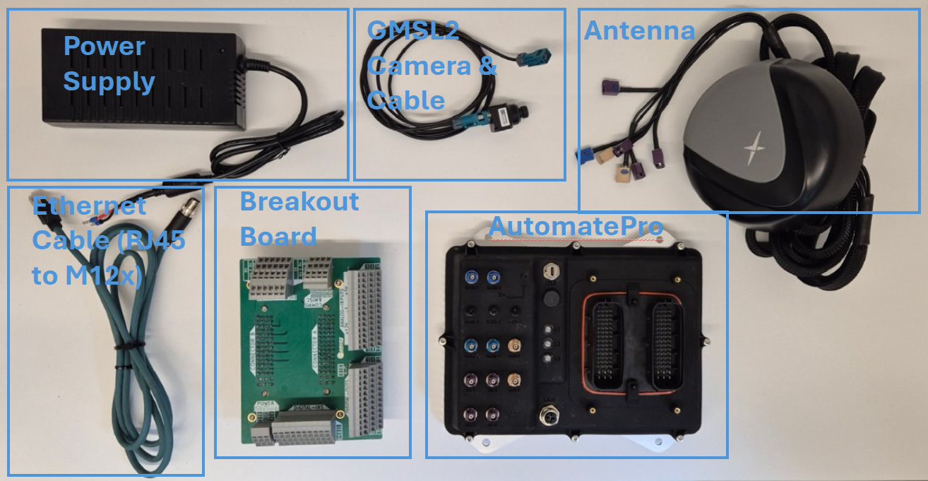
The exact contents depend on the configuration ordered. For this guide, assume the following components are included:
- AutomatePro main unit
- Power supply
- Ethernet cable
- Optional accessories (varies by configuration)
These are as follows:
Connecting AutomatePro
Hardware Connection
Use the provided power supply and Ethernet cable to connect your AutomatePro device, as shown in the illustrations below.
-
Connect the breakout board, if applicable.
If your configuration includes a breakout board, securely attach it to the AutomatePro unit. Ensure all pins are properly aligned before applying pressure to avoid damage.
-
Connect FAKRA antennas and cameras.
Attach GNSS, Wi-Fi, 5G, and camera FAKRA connectors to their designated ports. The connectors are color-coded for easy identification. Make sure each connector is fully inserted and securely locked to ensure a stable and reliable connection.
-
Connect Ethernet.
Use the supplied Ethernet cable to establish a wired network connection. Insert one end into AutomatePro and connect the other end to your router, switch, or development network.
-
Connect power.
Plug the provided power supply into AutomatePro. Ensure the connector polarity aligns with the labeled indicators to prevent improper connection.
-
Power on AutomatePro.
Once all connections are in place, turn on the power supply to start AutomatePro. The device begins its boot sequence and the status LEDs start blinking. Refer to the Status LED functions for more information on interpreting LED behavior.
Accessing AutomatePro
Once powered on and connected to the network, AutomatePro receives an IP address from your network's DHCP server. You can identify this IP address by checking the DHCP client list on your router, or by using a network scanning tool such as nmap or arp-scan to detect connected devices on your network.
After locating the IP address, you can access AutomatePro through either SSH for command-line access or Remote Desktop for graphical access.
SSH (Command-Line Access)
Use SSH for command-line access:
ssh admin@<ip-address>
Default credentials:
username: admin
password: password
Change the default password after the first login.
Remote Desktop (Graphical Access)
For graphical access, follow the Remote Desktop Guide.
To configure Wi-Fi, refer to the Wi-Fi Setup Guide.
Verify the System
Run these checks from an SSH session on AutomatePro.
-
Confirm the main services are running:
systemctl status automatepro-core-driver automatepro-io-agent automatepro-foxglove-bridgeHealthy services show
active (running). If a service is stopped, inspect logs with:sudo journalctl -u automatepro-core-driver -n 100 --no-pager -
Confirm ROS 2 can see the driver nodes:
source /opt/ros/humble/setup.bash
ros2 node list
Depending on the installed hardware options, you should see nodes such as:
/automatepro_driver_manager
/automatepro_gnss_position_node
/automatepro_gnss_heading_node
/automatepro_imu_driver
/automatepro_cam1_node
/automatepro_cam2_node -
Confirm common sensor topics are present:
ros2 topic list | grep -E '/sensor/imu|/sensor/gnss|/camera/.*/image_raw|/io/'Optional hardware only appears when that hardware and its driver are enabled.
For service management, configuration paths, package installation, and log commands, see Software Services.
Foxglove Interface
AutomatePro can be monitored and controlled using Foxglove Studio, a powerful visualization and observability tool designed for robotics applications.
-
Install Foxglove Studio.
Download and install Foxglove Studio from the official website. Follow the installation instructions appropriate for your operating system.
-
Import AutomatePro dashboards and extensions.
Download the AutomatePro Foxglove extension and preconfigured dashboards from the automatepro_foxglove repository. Import both into Foxglove Studio by following the steps in the video tutorial below or in the repository documentation.
-
Connect Foxglove Studio to AutomatePro.
Connect Foxglove Studio to AutomatePro by entering the IP address and default bridge port in the connection dialog:
ws://<ip-address>:8765