Small USV
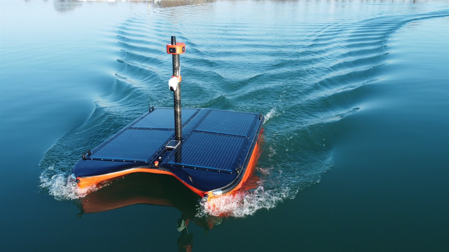
This reference design shows how AutomatePro can be used as the central compute, navigation and vehicle-control platform for a small electric USV. The example uses a twin-thruster catamaran with RTK positioning, two 196° GMSL2 cameras for 360° coverage, a marine radar, a deployable multibeam sonar, remote connectivity and basic vessel-management functions.
The design is intentionally kept simple. It is intended to show a practical starting architecture rather than prescribe a specific hull, motor controller, radar or sensor manufacturer. Component ratings, protection and regulatory requirements should be verified for the final vessel.
Overview
Features
The example vessel is intended to support:
- Differential-thrust electric propulsion
- Autonomous waypoint navigation and station keeping
- RTK GNSS positioning
- Differential GNSS heading (included in this example; optional on AutomatePro)
- Full 360° camera coverage from two 196° GMSL2 cameras
- Onboard segmentation and classification on the camera streams
- 5G / Wi-Fi remote connectivity
- Ethernet-connected marine radar
- Multibeam sonar on a dedicated sonar PC
- Powered sonar lift and deployment mechanism
- Port and starboard bilge monitoring and pumping
- Navigation lights
- External emergency-stop circuit
- 48 V nominal vessel power system (could also be a 24 V system)
The main objective is to minimize the number of separate compute, communications and I/O modules required in the vessel by using the functions already integrated into AutomatePro.
USV Compute and Control System Overview
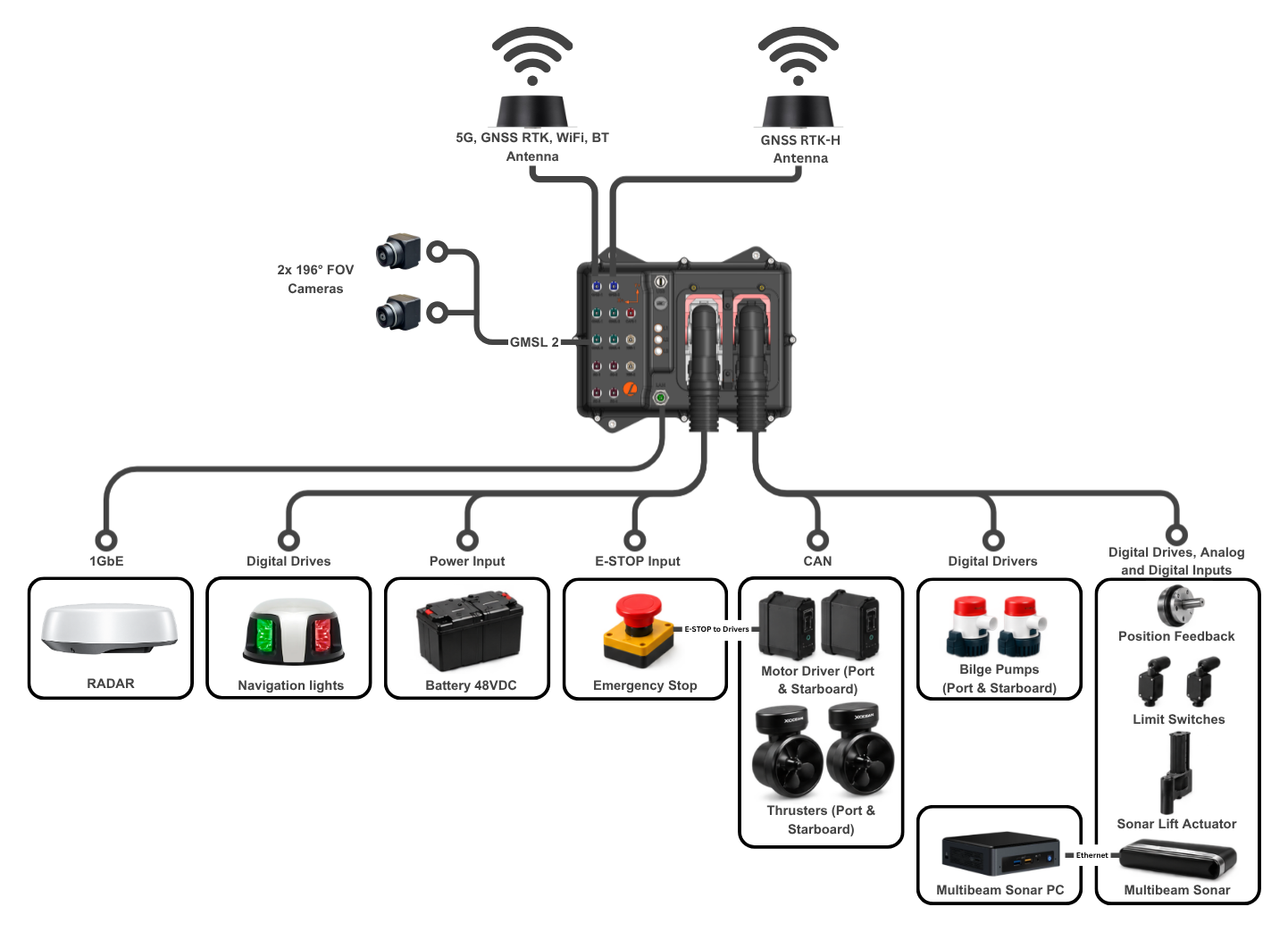
Resources
Key System Specifications
| Parameter | Value |
|---|---|
| Vessel type | Twin-hull electric catamaran |
| Propulsion | 2 × electric thrusters with differential thrust, CAN motor controllers |
| Power system | 48 V nominal battery, with the AutomatePro onboard 12 V and 5 V outputs for auxiliary loads |
| Navigation | RTK GNSS, 9-axis IMU, differential GNSS heading |
| Cameras | 2 × 196° GMSL2, forward and rear, for full 360° coverage |
| Radar | Ethernet marine radar |
| Survey payload | Multibeam sonar on a powered lift, run by a dedicated sonar PC |
| Communications | 5G / 4G, Wi-Fi, and Bluetooth |
| Vessel management | Port and starboard bilge monitoring and pumps, navigation lights, external E-STOP |
System Overview
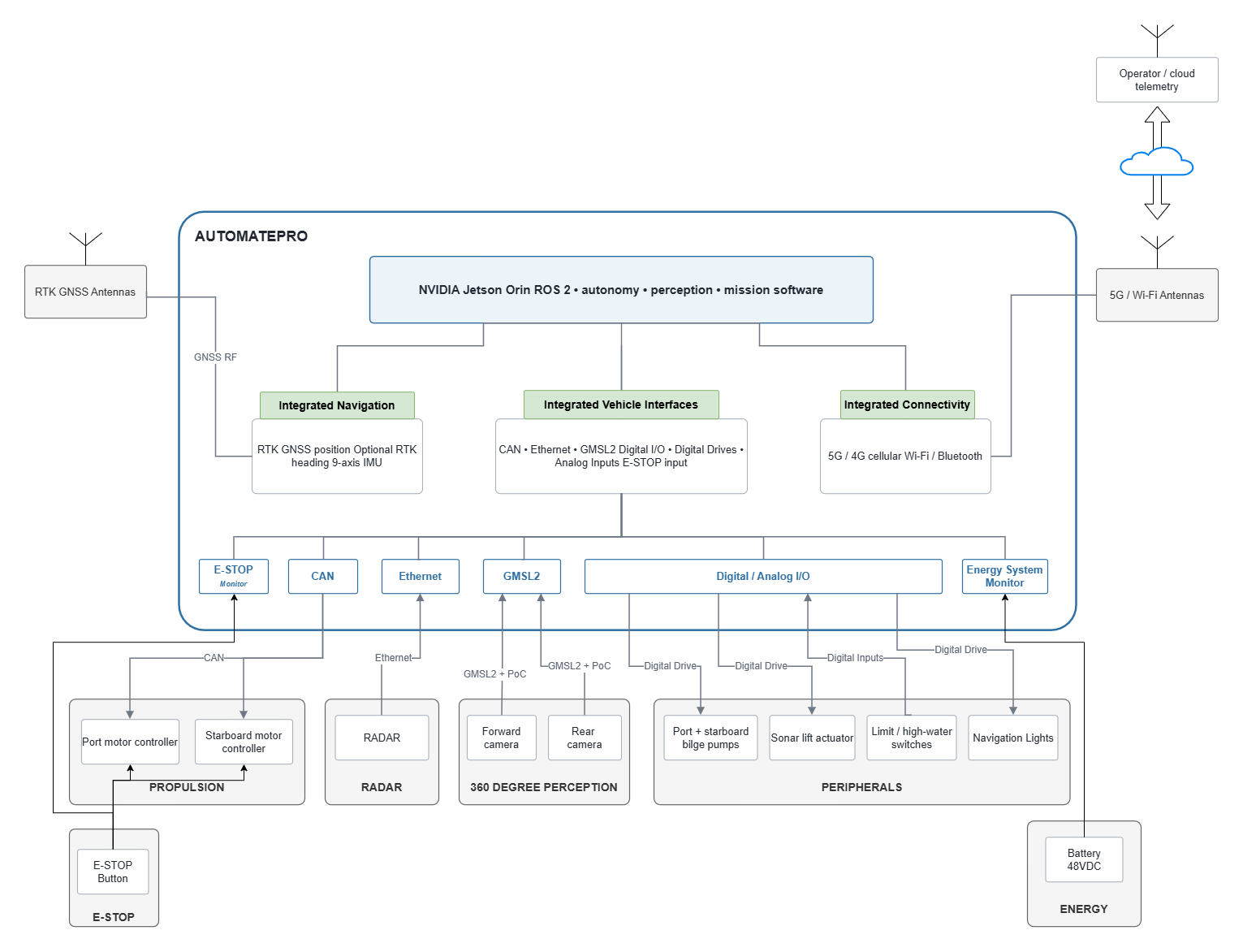
Block Diagram
The diagram shows the functions integrated into AutomatePro inside the blue boundary and the vessel hardware outside it.
AutomatePro Resources Used
The table shows which AutomatePro interfaces this design uses and how many remain free for additions. Channel assignments can be changed in software and in the vessel harness. For the full product specification, see the AutomatePro System Overview.
| Interface | Available | Used | Used for |
|---|---|---|---|
| GMSL2 camera inputs | 2 | 2 | Forward and rear 196° cameras |
| CAN | 1 | 1 | Port and starboard motor controllers |
| 1GbE Ethernet | 1 | 1 | Marine radar |
| RS485 | 1 | 0 | Spare |
| Digital Drives | 12 half-bridges | 6 | Bilge pumps (2), navigation lights (2), sonar lift actuator as one full bridge (2) |
| Digital Inputs | 10 | 4 | High-water switches (2), sonar lift limit switches (2) |
| Digital Outputs | 12 | 0 | Spare |
| Analog Inputs | 14 | 1 | Sonar lift position feedback |
| E-STOP input | 1 | 1 | External E-STOP monitoring |
| RTK GNSS and IMU | Integrated | Yes | Position and motion sensing |
| Differential GNSS heading | Integrated | Yes | Heading, using the second GNSS antenna |
| 5G, Wi-Fi and Bluetooth | Integrated | Yes | Remote link and local commissioning |
| 12 V and 5 V outputs | 12 V 8 A, 5 V 3 A | Yes | 12 V to ACTU_PWR for the Digital Drives, plus sensors and electronics |
Propulsion
The reference vessel uses two independently controlled electric thrusters, with each motor controller connected to AutomatePro via CANopen. Differential thrust provides both propulsion and yaw control without a separate rudder.
See CAN Bus for wiring and interface configuration.
Propulsion E-STOP
The external E-STOP should be wired directly into the propulsion-controller safety or inhibit circuit where supported. The same E-STOP state can also be connected to AutomatePro so that software can monitor the vessel state.
The AutomatePro E-STOP connection is an input and is not a safety-rated function. It should not be used as the only safety mechanism for propulsion shutdown. Use the safety inputs and architecture required by the selected motor controllers and vessel risk assessment.
When the AutomatePro E-STOP input is low, AutomatePro also disables its Digital Drive outputs. See E-STOP and Digital Drive Out.
Payload
Multibeam Sonar
The multibeam sonar runs on a dedicated sonar PC, keeping survey software separate from vessel control. AutomatePro controls deployment and retraction using the sonar lift.
Sonar Lift
A reversible linear actuator deploys and retracts the sonar. AutomatePro uses:
- Digital Drive — actuator direction and speed
- Digital Inputs — upper and lower limit switches
- Analog Input — continuous position feedback
The sonar is normally retracted during launch and transit, deployed for survey operations, and retracted before returning to transit mode.
See Analog Input for position feedback configuration.
Bilge System
Each hull has a high-water switch and a bilge pump. The pump can be activated in two ways:
- Automatically: the high-water switch directly activates the corresponding bilge pump
- From AutomatePro: the control system can command the pump through a Digital Drive
AutomatePro also monitors the high-water switches through Digital Inputs, allowing it to raise warnings and remote alarms.
This means the bilge pumps can still respond directly to rising water, while remaining controllable and monitorable by the vessel software.
If the pumps must remain operational during an E-STOP, the automatic bilge circuit should be independent of the AutomatePro Digital Drives.
The onboard 12 V supply feeds ACTU_PWR for the sonar lift, bilge pumps and navigation lights. All connected 12 V loads share its 8 A limit, and each Digital Drive has a 5 A limit. Size the loads for simultaneous operation, including pump starting current and actuator stall current. If these limits cannot be met, use a suitably rated external 12 V supply and, where necessary, an external actuator drive.
See Digital Drive Out for configuration.
Cameras and Perception
The reference design uses two 196° GMSL2 cameras connected directly to AutomatePro, one facing forward and one aft. Together, they provide full 360° coverage for navigation, docking, situational awareness and remote operation.
Mount the cameras with unobstructed views and overlapping coverage on both sides of the vessel.
Segmentation and classification models can run directly on the NVIDIA Jetson in AutomatePro to detect vessels, buoys, obstacles and shoreline features onboard.
GMSL2 provides a robust, low-latency connection with Power over Coax.
See GMSL2 Camera.
Radar
A marine radar connects directly to the AutomatePro 1GbE port and feeds the perception and collision-avoidance software on the Jetson, alongside the cameras. Check that the selected radar provides a Linux or ROS 2 driver.
The AutomatePro Ethernet port does not provide PoE, so the radar needs its own power supply. See Ethernet for the network interface specification.
Position, Heading and Connectivity
RTK GNSS, IMU, cellular and local wireless connectivity can be integrated directly in AutomatePro, reducing the number of separate modules that need to be packaged and wired in the vessel.
For this reference design:
- RTK GNSS provides global position for navigation.
- The integrated IMU provides angular-rate and acceleration measurements.
- This example includes the optional differential GNSS heading receiver and a second antenna, with at least 1 m separation between the GNSS antennas.
- RTK correction data is received from a correction service over the cellular or Wi-Fi connection.
- 5G provides the primary near-shore remote communications link where network coverage is available.
- Wi-Fi provides local commissioning, service and short-range communications.
Related documentation:
Power Architecture
The reference vessel uses a 48 V nominal propulsion battery.
AutomatePro supports a wide DC input range; the current product documentation specifies a recommended supply range of 16–58 VDC. The actual maximum charging voltage of the selected 48 V battery chemistry must therefore be checked against the AutomatePro input limits.
A practical power arrangement is:
| Rail | Typical loads |
|---|---|
| 48 V nominal propulsion bus | Propulsion controllers, main vessel power |
| AutomatePro main input | Direct from vessel bus where the full battery voltage remains within specification |
AutomatePro onboard 12 V output, to ACTU_PWR | All Digital Drive loads: sonar lift actuator, bilge pumps and navigation lights, plus 12 V sensors and electronics, up to 8 A in total |
| AutomatePro onboard 5 V output | 5 V sensors and electronics, up to 3 A |
The onboard 12 V output can supply the auxiliary loads without a separate converter where the power budget permits. All Digital Drive loads and 12 V sensors share its 8 A limit. Check simultaneous loads, pump starting current and actuator stall current against this limit and the 5 A limit of each Digital Drive; use an external supply or drive where required.
The system illustration intentionally omits fuses, contactors, DC/DC converters, isolation, distribution blocks and protective devices to keep the reference architecture readable. These must be sized and added for the final vessel design.
Software Architecture
A simple ROS 2 software structure for this vessel could separate the system into the following main functions:
AutomatePro includes ROS 2 drivers for supported onboard sensors and I/O, allowing application software to interact with the system without implementing low-level hardware drivers from scratch.
Optional Extensions
The architecture can be expanded without changing the basic system concept. Examples include:
- LiDAR over Ethernet
- AIS receiver
- NMEA 2000 marine instruments over CAN
- Serial sensors and instruments over RS485
- Additional warning beacons or buzzers
- Satcom, such as Starlink or Eutelsat OneWeb
- DockMaster integration for autonomous docking and charging
For larger vessels or higher-power auxiliaries, external contactors, motor drives and protected power-distribution modules should be used, with AutomatePro providing commands, sensing and supervisory control.
To discuss any of these extensions or a higher-power configuration for your vessel, contact Lemvos.
System Components
Lemvos Products
| Product | Part number | Qty | Role in this design |
|---|---|---|---|
| AutomatePro | AMP10-NO08-5G1-WIFI1-GMSLA-SSD1-RTKH-AIN1-NA | 1 | Central compute, navigation and vehicle control |
| Sony ISX031 GMSL2 Monocular Camera | AMP-1003-196F | 2 | Forward and rear 196° cameras for 360° coverage |
| Camera Mount / Feed-Through / Shade | AMP-1011 | 2 | Sealed camera mounting through the deck or hull |
| FAKRA Type Z Camera Cables | AMP-1007 | 2 | Camera connections to the GMSL2 inputs |
| 7-in-1 Combination Antenna | AMP-1001-3M | 1 | 5G, Wi-Fi, Bluetooth and RTK GNSS positioning |
| RTK GNSS Antenna | AMP-1002-3M | 1 | Second GNSS antenna for differential heading |
| M12x to RJ45 Cable | AMP-1006-2M | 1 | Ethernet connection to the marine radar |
| Main Connector and Crimp Kit | AMP-1009 | 1 | Vessel wiring harness |
Third-Party Components
Third-party components are described by type, so the design can be adapted to different vessel sizes and suppliers. Lemvos can help you narrow down and select suitable components for your application. Contact Lemvos to discuss your requirements.
| Component | Requirement | Qty |
|---|---|---|
| Motor controllers | CANopen electric motor controller | 2 |
| Electric thrusters | Matched to the motor controllers | 2 |
| Marine radar | Ethernet radar with a Linux or ROS 2 driver | 1 |
| Bilge pumps | 12 V DC pump | 2 |
| High-water switches | Float or solid-state level switch | 2 |
| Navigation lights | 12 V LED, port and starboard | 2 |
| Sonar lift actuator | 12 V reversible linear actuator | 1 |
| Sonar lift limit switches | Upper and lower limit switch or proximity sensor | 2 |
| Sonar lift position sensor | 0–10 V position transducer | 1 |
| Multibeam sonar | Multibeam survey sonar | 1 |
| Sonar PC | Dedicated computer running the sonar acquisition software | 1 |
| Emergency stop | Latching external E-STOP, wired to the propulsion inhibit and the AutomatePro E-STOP input | 1 |
| Vessel battery | 48 V nominal, with maximum charge voltage within the AutomatePro input range | 1 |